On the evening of 18 January 1978, nearly 5,000 spectators watched a basketball game in the three-year-old Hartford Center. It was the jewel of an urban renewal program in the city of Hartford, Connecticut, and boasted the largest single span of roof ever lifted into place as a complete unit. The roof was an engineering marvel, designed with the aid of a computer modeling program; it was an innovative “space truss” roof that was purported to be lighter and stronger than traditionally built roofs.
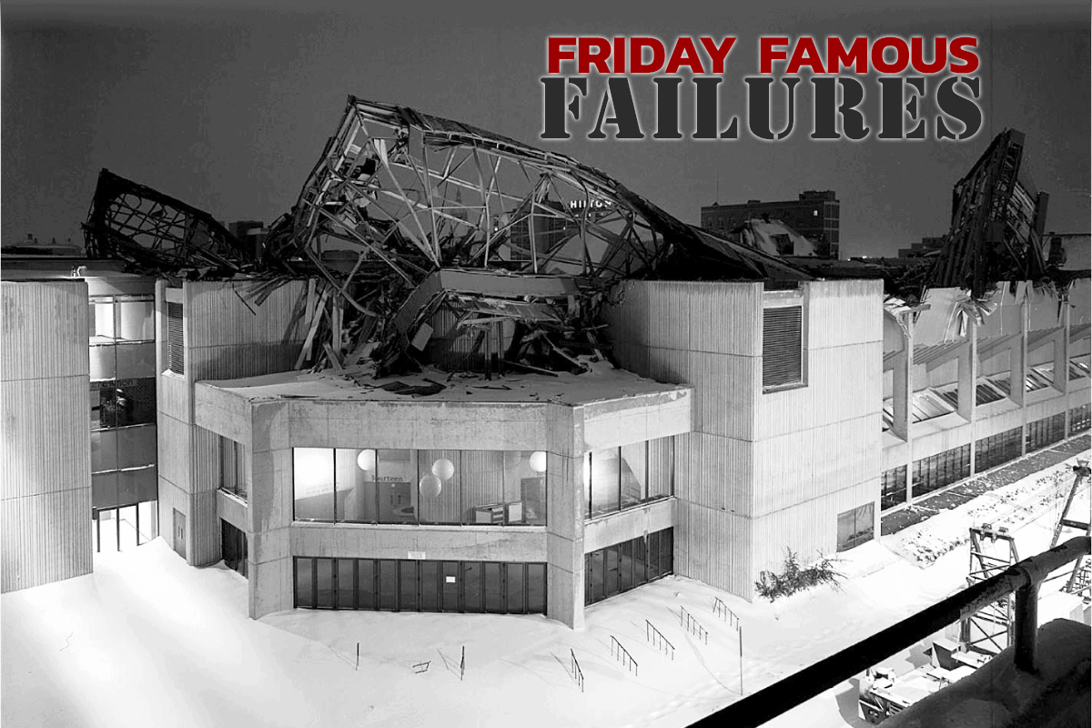
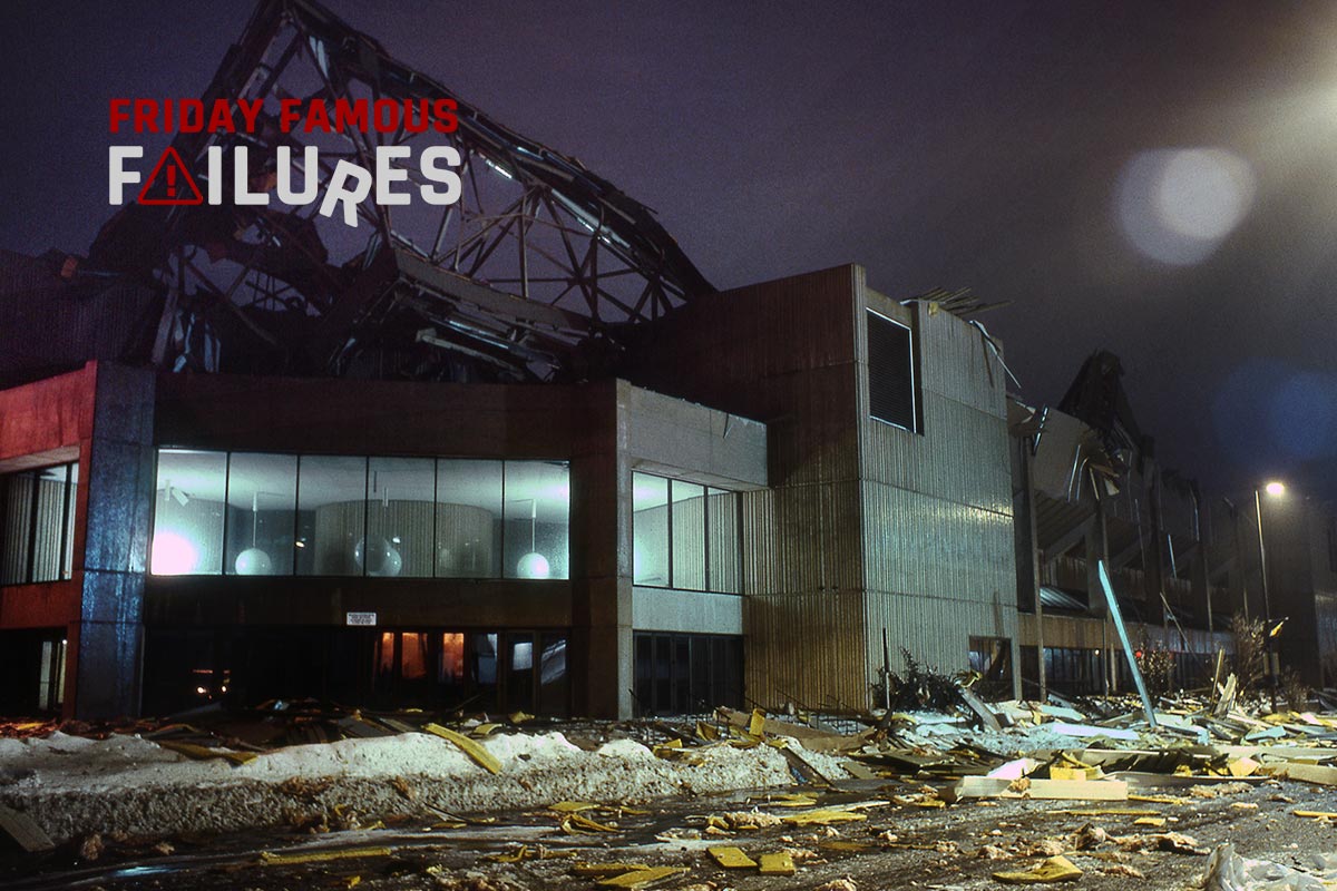
But six hours later, the 2.5 acre, 2,900-ton roof of the Hartford Center collapsed entirely, falling as a whole unit more than 80 feet to the arena floor and seating areas within a few seconds. Fortunately, the building was unoccupied during the fall, and no one was injured. But what would cause the entire roof to fall down the way it did?
What caused this disaster?
Use of cruciform truss members. Each chord of the space frame was made of four lengths of steel with an L-shaped cross-section, joined back-to-back to create a single length with a cruciform cross-section. These assembled members had much poorer resistance to buckling than I-shaped or tubular chords.
Missing trusses to brace the “top chords.” The elements of the space frame were inverted octahedral shapes (pyramids with a four-sided base), where the four “top chords” made a square with 30-foot lengths. The computer simulation anticipated that the top chords would be laterally braced with a truss joining the midpoints of opposing chords, but these additional braces were not actually built into the roof.
Suspension of the roof above the frame. The concrete roof itself was suspended above the space truss frame by metal posts of various heights, so the roof had positive drainage. These posts became localized stressors on the space frame below. Suspending the roof also eliminated any additional bracing the roof would have provided to the top chords.
Increased weight of the roof. During construction, the contractor changed the roof material, which made it 20% heavier than originally designed.
Off-center truss connections. As designed and modeled by the computer, the diagonal components of the octahedrons were to be joined directly to the center of the top chords. However, the contractor actually joined the diagonals underneath the top chords, greatly weakening the effect of the bracing.
Effects of the disaster
Problems with the Hartford Center roof were evident from early construction. During the erection of the truss, a contractor recorded that the bottom chords were distorted more than 8.4 inches by the weight of the truss itself. This exceeded the expected distortion of 7.35 inches, a calculation that included the expected weight of the concrete roof (which was not yet installed). Later, when lighting, HVAC, and the heavy four-sided scoreboard were suspended from the roof, the truss distortion measured more than 12 inches despite the fact that design calculations showed a maximum of 8.5 inches distortion under that load.
During construction, many guests at the 22-floor Sheraton hotel, which had a clear view of the construction area and the completed structure, noticed a visible “sag” or “dimple” evident in the roof. Some ironworkers involved in construction complained the building was a “death trap” and vowed never to set foot in the building, but their concerns were dismissed by construction management. Concerns about the project were raised all the way to the mayor of Hartford, but he was convinced by contractors that some distortion was expected. The mayor joined contractors in assuring the community that there was no cause for concern.
After the collapse, steel cables were discovered amid the wreckage of the truss and the roof. These steel cables were not part of the original design, and the engineers and architects who designed the building were never informed of their installation. They were clearly, however, designed to hold the roof together, which means that at least one of the contractors was aware that the roof was defective. Investigators speculate that the cables were installed secretly in response to concerns raised by nearby hotel guests, and their effect was to “pull” the roof back into the correct shape. But none of the involved contractors admitted to installing the cable.
The city of Hartford hired Lev Zetlin Associates, Inc. to investigate the disaster. They concluded that progressive lateral buckling, or bending, of the top chords caused the roof to collapse. Reviewing the computer-aided design of the frame, and assembling evidence from the wreckage, Charles Thorton, chief engineer investigating the accident, demonstrated how the design flaws had drastically reduced the strength of the space frame:
- Chord members with a cruciform cross-section are much more susceptible to buckling when they are assembled in compression, as were the chords of the space frame;
- The absence of cross-bracing at the midpoints of the top chords reduced their resistance to lateral buckling by 75%;
- The top chords, between the extra weight of the roof and lack of bracing, were overloaded from 72% to 852% of their design strength depending on their location in the roof structure.
Another firm investigating the collapse, Loomis and Loomis, Inc. (LLI), agreed with Thorton’s report that significant design flaws caused the progressive deterioration of the roof until it failed. However, their own computer models of the roof as built indicated that the diagonal chords of the space frame suffered torsional buckling, or twisting, which caused the collapse. Their computer models indicated that only 12 to 15 more pounds per square inch (psi) of load on the roof would have caused it to collapse, which was the case on the night of the incident as snowfall on the roof would have added 14 to 19 psi of load. This model also predicted a bottom-chord distortion of 11.7 inches, which nearly matched the actual distortion of 12 to 13 inches observed by investigators. LLI concluded the roof would have collapsed even if the top chord members were not missing top braces.
Whether the lateral buckling of the top chords or the torsion buckling of the diagonals precipitated the roof collapse, both reports agree that the roof was basically non-viable from the choice to use chords with a cruciform cross-section. The engineering firm responsible for the design never explained the choice to use cruciform members, but it may have been to avoid paying royalties on previous space frame patents, which used tubular sections, notably by Buckminster Fuller and Alexander Graham Bell.
But whatever the flaws in design, the excessive distortion observed during construction was faithfully reported to the design engineer, who was so confident in the computer model used to design the truss that he never checked his work – and he never discovered how the truss as-built differed from the computer model. The result of this collapse was the emergence of “best practices” in computer design where models are peer-reviewed by a disinterested third party to avoid mistaken assumptions in the program, which today is the law when designing buildings in Connecticut.


Who allowed the contractor to make changes in the field during construction ?
Why didn’t the Inspectors make note of the changes and issue NCR’s ?
Who reviewed and approved the shop drawings of the steel framework ? Were any changes or deviations from the design indicated in the shop drawings ?
This goes back to the old adage that garbage in gives garbage out. I am from the old school. I used to make the PE provide at least one hand calculation to check to make sure a computer generated design was checked. The new generation of PE’s take the belief that this is what the computer told me. Has the PE checked how the computer generated design calculations were used. I doubt it.
Computers are good to perform rapid calculations but we as PE’s need to protect the public as best as possible and take responsibility of the designs we sign and seal
A lower scaled model should have been built and inspected.
A great article which would be even greater with a few pictures key structural components.
I have a friend who is not a PE who designs complex conveyor systems. He has butted heads with PE’s over the years who are not well-versed in his specialty. His comments on those occasions is that some people think “PE” means “preserved from error”. This example does nothing to dispel that notion. No one likes to believe they may have goofed on a design or calculation, but prudence requires us to genuinely review our work in light of any criticism, bearing in mind that the public safety is often involved.
The main cause of hte collapse was the use of the crusiform members – but the addtion of an additional angle to the crusiform to “box in” one of the angles in the crusiform could have prevented the torsional buckling. Note that it is only for some angles in this shape that torsional buckling is a problem. If the angle legs are thin, then local bucling controls. If they are thick, then euler buckling controls for these sections. It is a range between these that results in torsional buckling controlling. For me, the “big” error during construction was not investigating why the deflections were so high under the dead load alone. It was much higher than the designer’s computer results. I was one of the people who investigated the collapse, my father Robert S. Loomis was the prime author of our paper on the collapse. Torsional buckling is now included in the AISC code, it was not at the time of this failure.
That must have been some super dense snow, at 14 to 19 psi. Or it was 200 feet deep. The units for snow load are supposed to be psf, not psi.
Where was the PM and inspectors? It is hard to believe that so many “field” changes were made but apparently not checked for affect. Beauty is not necessarily a good design. Fortunate no one was injured or killed!
Outstanding example why failures are frequently called a cascade of events. It appears that almost everyone involved in the design and construction of this structure screwed up.. There were several issues here that should have raised major red flags, as some of these during construction events made it blindingly obvious that this structure was built to fail. Excessive deflection should have been the first red flag and should have brought everything to a screeching halt on the “why” was found and corrected. Generally normal safety factors in design will result in less than anticipated deflection, and certainly not more. Bracing not installed? Where were the inspectors? The addition of the cables and there denial by everybody says that the contractor(s) realized the structure was in trouble, but these turned out to be little more than bandaids over a cancer. Getting the contractor and mayor to affirm the safety of the structure is like getting a plumber and a lawyer to deny that your medically diagnosed cancer is real. Etc., etc.
Could have been dense wet snow, as is fairly common around here, or worse, a layer of ice from freezing rain immediately after the wet snowfall!
First comment above is the best. The contractor effectively changed the design by changing the way the trusses were connected. Who approved that change? And the contractor changed the weight of the roof? Who approved that change? Sounds to me more like construction inspection and contractor failures than design errors. And by the way, “L” shaped sections can be effectively used in compression as long as they are properly designed.
One additioinal comment. The cables that were installed had nothing to do with strengthening the structure. The painter installed them to use as safety lines and didn’t remove them. This came out during the investigation.
I’m saying the units are wrong. Ice would have to be 30+ FEET thick to weigh 14 pounds per square inch.
Thank you to all the content creators and commentors. I am especially grateful to Mr Loomis for your first hand input to the conversation.
I agree with the comment that a full scale model should have been built to show the complexities of this design. Models may not show the loading of individual support members but they do show the connection of each member and they can show how each section is supported or provides support for another.
I noticed it too. They should edit the article to make the correction.
I too am old school in requiring my engineers to prove some of the computer output. I cannot count the number of engineers that tell me “Well, that is what the computer program produced so it must be ok.”
After a few checks of the inputs, or finding out that the analysis was taken to the limits (or beyond) of the program’s correlations do the engineers admit they should have done a better job.
I always told my young engineers that they get paid for validating assumptions and design inputs; not just punch in numbers and watch the machine crunch the analysis.
In building or bridge construction the chief engineer has to be sure the design and specs are being followed. While others like the PM and inspectors do most of the verification, the Engineer has to be visibly checking the checkers on a regular basis. It is a recurring theme of these failures that contractors are not following specs. Also I agree completely with the comment of over-reliance on computer models. While complex problems are often beyond back of envelope checks now, given the life safety responsibility, Engineers have to have others review their work, ideally with a different program simulation.